Motor Testing System
Project Description
Design Challenge
For our capstone design project, we connected with an industry client doing electric motor development. They needed to measure motor torque vs speed performance with a dynamometer. However, they also wanted to simultaneously put the motor and its housing under realistic service loads, including large axial forces on the motor shaft.
They challenged us to design & build a system that could apply precise, measureable axial loads to the motor shaft while the motor is attached to the dynamometer. They emphasized that the loads had to be well-aligned to the shaft axis, with no bending moments on the motor shaft.
Result
The project was a huge success. We were able to meet all our client’s needs and delivered the finished product to them on time. Here is the brochure we handed out at our final design presentation:

Front of our tri-fold brochure for presentation day (graphic design by my teammate Scott).
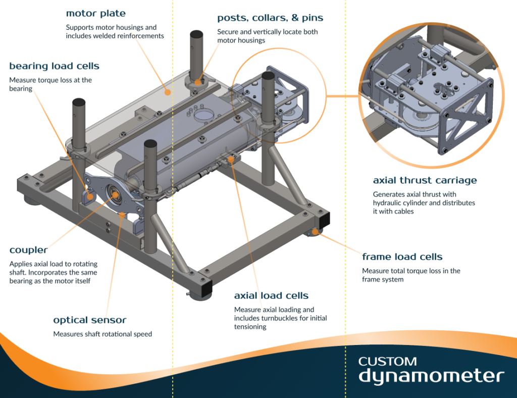
Back of our tri-fold brochure for presentation day (graphic design by my teammate Scott).
My Contribution
Axial Thrust System
I was in charge of the axial thrust subassembly. I used a bolt pattern on the backside of the client’s motor housing to hang the ‘carriage’. That bolt pattern is precision-machined, so it guarantees good alignment with the shaft axis. The carriage sits on four linear bearings, so it has 1 degree of freedom — translation along the shaft axis. A linear hydraulic actuator in the carriage pushes against the backside of the motor housing, forcing the carriage outward. There is a single cable that wraps over a pair of pulleys in the carriage, and connects to either side of the coupler at the front of the motor. When hydraulic pressure is applied to the actuator, the carriage is pushed out, pulling tension in the cable. The cable applies an equal load to either side of the coupler, and the coupler pushes on the motor shaft through a thrust bearing.

CAD model of the axial thrust sub-assembly.
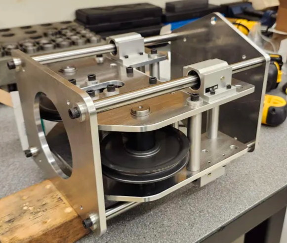
Finished axial thrust sub-assembly.
Video demonstrating smooth carriage movement.
Try this link in case the video embed isnt working,
or use a different device/browser.
Design Choices
- I chose the Enerpac Hydraulic Cylinder because it exceeded the loading requirements, and its small area is ideal for pressure-based control. Its small profile and external threads made it excellent for integrating into the rest of the assembly.
- The entire assembly uses 1/4″-28 x 5/8″ socket head cap screws (except for the linear bearings that required smaller). These were slightly oversized in most areas of the assembly, but I chose simplicity over weight/space savings since this is a test bench.
- I chose 6061-T6 aluminum for most of the machined components. It had more than enough strength and is accessible and easily machinable.
- I chose precision ground, hardened steel for the linear motion shafts to guarantee smooth, precise motion.
- Since the pulleys are statically loaded on needle roller bearings, their shafts are also precision ground, hardnened steel. The static loading on the needle rollers would cause shaft surface pitting with a softer material.
- The carriage and the linear bearings were made with a ‘post-and-plate’ design method, where posts were stepped down to slip-fit into their mating holes. Thick aluminum washers are used and the bolt pulls everything together tight. This method was very effective for keeping everything square.
- 1/4″ ultra-flex cable was attached to load cells on either end, and each load cell was attached to a turnbuckle to allow adjustment/pretension. The turnbuckle ends attach to the coupler (see brochure).
- The stored energy in the cable poses a serious risk of injury if it were to fail. For that reason, I sourced the cable, turnbuckle, and pulleys from McMaster Carr. McMaster is a trusted hardware supplier, and they provide load ratings, drawings, and accutate CAD models. This made it easy to put together a cable assembly that I could be confident in. I also purchased extra to proof the test cable assembly on an MTS machine.
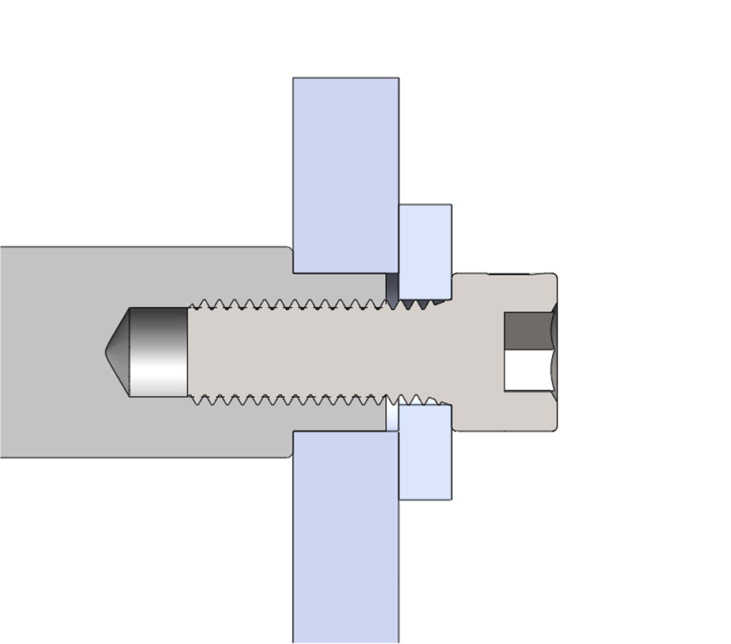
Post-and-plate cross section
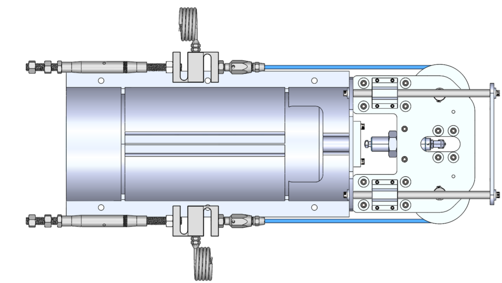
Top view with cables highlighted
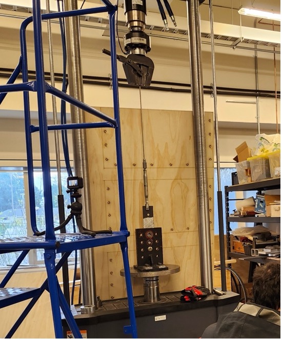
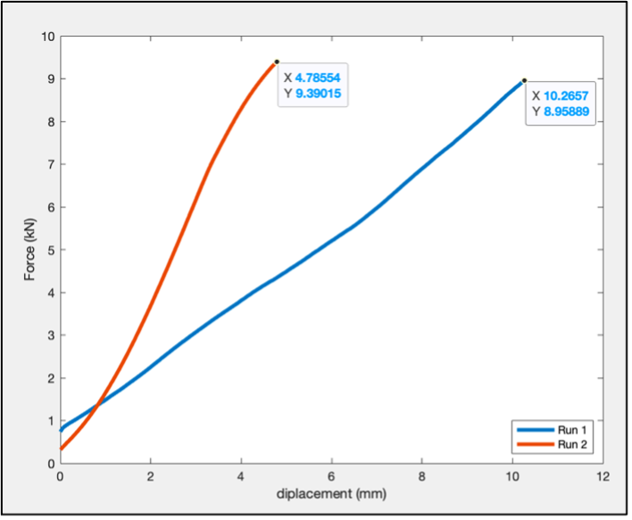
Cable proof testing & results. The client required 2.2kN capability. I ran the test twice, both times to 9kN.
The first run shows more displacement because the cable is settling into its wedge-lock
attachment to the clevis (this was expected per manufacturer’s documentation).